What is Transformer? | Definition, Working and Types of Transformer
Transformer Definition
So what is transformer after all? A simple transformer definition is that it is a static electrical device which transforms the electrical energy from one electrical circuit to another without any change of frequency through the process of electromagnetic induction. It is interesting to note that the transfer of energy from one circuit to another takes place with the help of mutual induction that is flux induced in the primary winding gets linked with the secondary winding which we shall explain in a while. Transformer Failure can also occur if appropriate care is not taken for it's operation.
The major role a transformer is either to step up or step down the voltage depending on situation where it is installed.
Working of transformer
The working of transformer is based on the simple principle of mutual induction between the primary and secondary windings which is otherwise known as coils, which helps for to transform the energy from one circuit to another. Now let’s try to understand the overall picture:
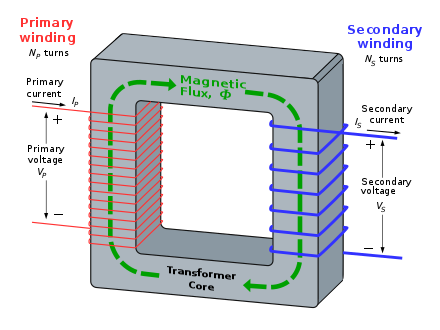
So in general the primary coil of the transformer receives the voltage which is alternating in nature. The alternating current following the coil produces a continuously changing and alternating flux which is produced around the primary winding. Then we have the other coil or the secondary coil which is near to the primary coil which get linked to the primary because some alternating flux gets linked. As the flux is changing continuously it induces a EMF induced in the secondary coil according to the Faraday’s law of electromagnetic induction. If the secondary side circuit is closed a current will flow and this is the most basic working of a transformer.
Construction of 3 phase transformer
The three main part of any transformer are the primary winding, secondary winding and the magnetic core. We shall now into each of this components in detail.
Primary Winding
This is the main winding where the incoming alternating current is expected. Depending on the fact that the transformer is either a step up or step down transformer the winding construction changes accordingly.
Secondary Winding
This is the winding in which the flux produced by the primary winding get linked. In this case also depending on the fact that the transformer is either a step up or step down transformer the winding construction changes accordingly.
Magnetic Core
This is required to provide a low reluctance path for the magnetic flux to flow from the primary winding to the secondary winding to form a close magnetic circuit. It is usually made up of CRGOS (Cold Rolled Grain Oriented Silicon Steel).
Transformer Equation
So now let’s look at the theoretical aspect of the transformer for this it is important for us to understand the transformer equation and how it derived and the various relationship that we have with regards to the voltage, turns and flux.
So let’s start…
The emf induced in each winding of the transformer can be calculated from its emf equation.

The linking of the flux is represented by the Faraday law of electromagnetic induction. It is expressed as,

The above equation may be written as,

where Em = 4.44ωΦm = maximum value of e. For a sine wave, the r.m.s value of e.m.f is given by
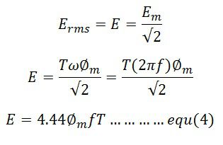
The emf induced in their primary and secondary winding is expressed as,
The secondary RMS voltage is

Where φm is the maximum value of flux in Weber (Wb), f is the frequency in hertz (Hz) and E1 and E2 in volts.
If, Bm = maximum flux density in the magnetic circuit in Tesla (T)
A = area of cross-section of the core in square meter (m2)

The winding which has the higher number of voltage has high voltage while the primary winding has low voltage.
Voltage Ratio and Turns Ratio
The ratio of E/T is called volts per turn. The primary and secondary volts per turns is given by the formula


The equation (1) and (2) shows that the voltage per turn in both the winding is same, i.e.
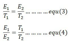
The ratio T1/T2 is called the turn ratio. The turn ratio is expressed as

The ratio of primary to secondary turn which equals to primary to secondary induced voltage indicates how much the primary voltage lowered or raised. The turn ratio or induced voltage ratio is called the transformation ratio, and it is denoted by the symbol a. Thus,

The any desired voltage ratio can be obtained by shifting the number of turns.
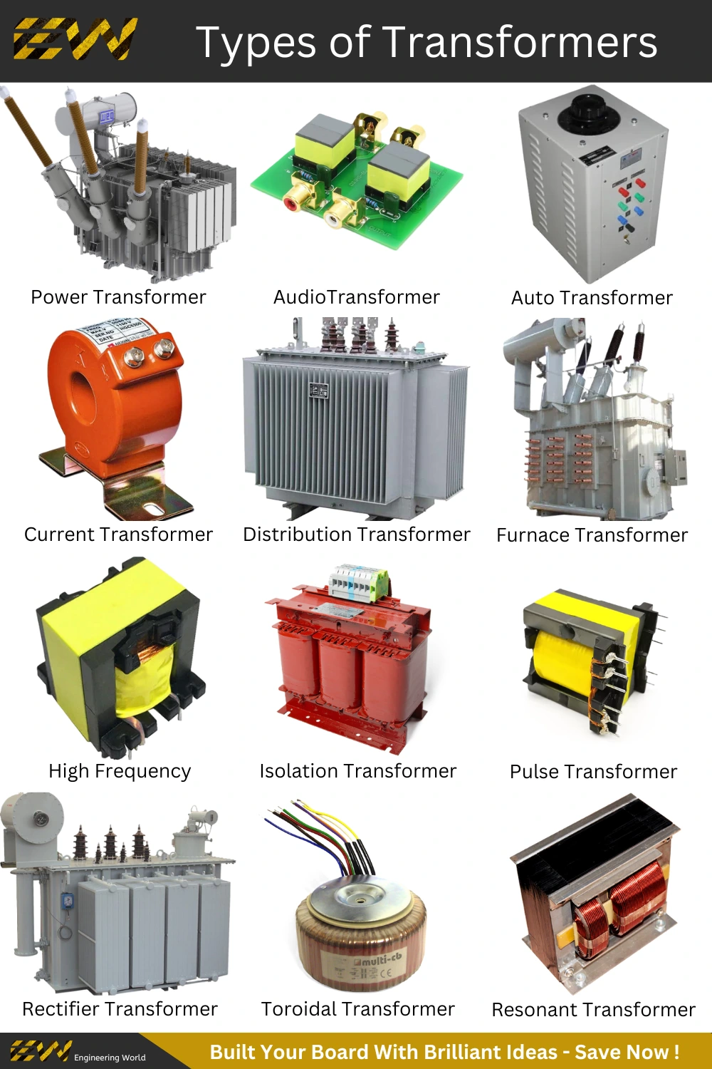
Types of Transformers
Since transformer are used in probably every field, they are various different kind of transformer depending on several factors like construction of transformer, application, area where it used in, end purpose of the transformer etc. etc.
We shall now look in to each of them in great details:Classification of transformer based on Voltage Levels
This is probably the most basic form of classification when it comes to transformers, whether it is a step up or step down transformer.
Step-Up Transformer
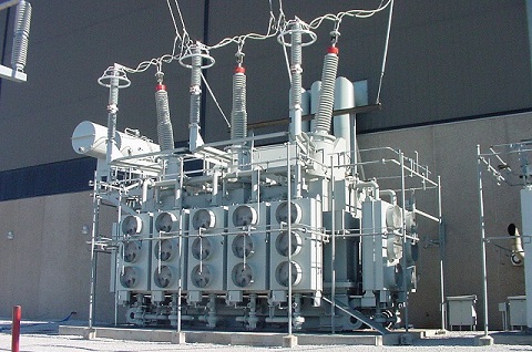
As the name suggest step up transformer are used to increase the voltage at the secondary side of the transformer. This is achieved by having more number of turns in the secondary side of the transformer as compared to the primary side of the transformer. Such type of transformer is generally used in the generating stations where the generator voltage typically at 23.5kV is stepped up to 132kV or more.
Step- Down Transformer
As the name suggest step down transformer are used to decrease the voltage at the secondary side of the transformer. This is achieved by having less number of turns in the secondary side of the transformer as compared to the primary side of the transformer. Such type of transformers is generally used in the distribution network where the grid voltage of 11kV is stepped down to 415V for domestic or commercial usage.
Classification of transformer based on Core Medium
Now depending on the core between the primary and secondary winding of the transformer winding the transformers are classified as Air core or Iron Core.
Air Core Transformers
The primary and secondary winding of the transformer are wound on a magnetic strip and the flux linkage between them is through the air. This type of transformers is generally not preferred since the mutual inductance is quite less as compared to the core because the reluctance offered by the air core is very high. But it is interesting to note that the hysteresis and eddy current losses are completely eliminated.
Iron Core
The primary winding and the secondary winding are placed on an iron core which provides a perfect linkage of the flux between the two. This type of transformer is generally preferred since it offers very less reluctance to the linkage flux due to its excellent magnetic property making the overall efficiency of the transformer much higher as compared to the air core transformer.
Classification of Transformer based on Usage
Transformer are further classified based on the application; we shall see each one of them in details:
Power Transformer
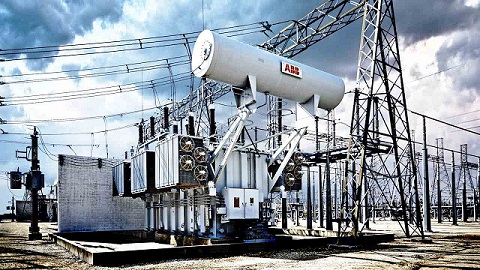
Are those transformers which are used in transmission network working at very high voltage levels and used for either stepping up or stepping down application. The voltage class includes 400kV, 200kV, 110kV, 66kV,33kV and are generally rated above 200MVA.
Since they are used for transmission purpose at heavy load and at voltages at more than 33kV they are big in size since the insulation required is high. They are also meant to work at 100% efficiency in order to avoid transmission losses.
For them to avoid the transmission loses or I2r losses they are deigned in such a way that the core is utilized to the maximum and will have the iron losses equal to the copper losses at leak load in order to achieve maximum efficiency.
Distribution Transformer
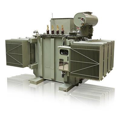
As the name suggests such type of transformers are used for lower voltage distribution networks as a means to provide power to the end user. The voltage class for the distribution transformer are 11kV, 6.6kV, 3.3kV, 440V and 230V and generally rated less than 200MVA.
This kind of transformer are either used to supply power to industries at 33kV or for domestic purpose at 415V. They work at lower efficiency of 50-70% and are small in size since the insulation required is less as compared to the power transformer.
Distribution transformer can be further classified based on type of insulation: Liquid Immersed Transformer or Dry Type Transformer
Liquid Immersed Transformer
This type of distribution transformer use oil as coolant inside the transformer body. The windings are immersed in the transformer and the insulation oil helps to maintain the temperature inside. It is to be noted that the insulating oil deteriorates over time and needs to be treated after sometime because the BDV (Break Down Voltage) value drops because of the formation of sludge in the oil.
Dry Type Transformer
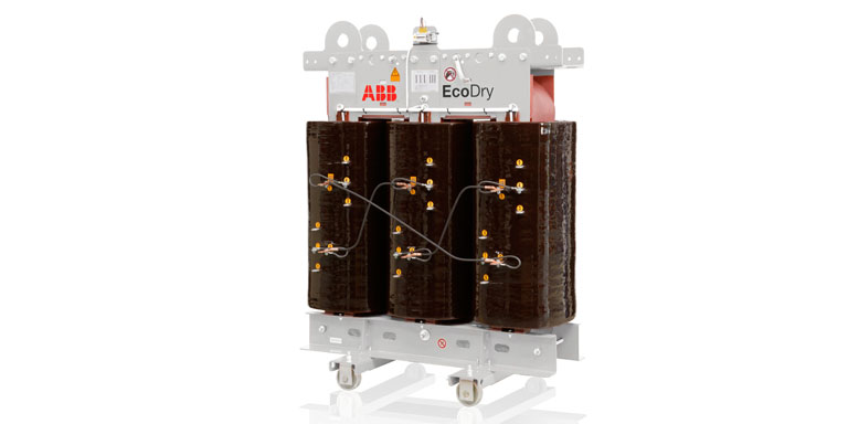
As the name suggests this type of transformers do use oil as insulating medium inside rather they are air cooled transformer and the windings are made of F and H class insulation. They generally preferred choice of transformer when the application is inside a building or in a place where safety is top priority. They are also very compact as compared to the oil immersed transformer since they don’t have radiators attached to them for cooling purpose. Depending on how they are cooled they are classified into two types:
Instrument Transformer
This type of transformer is used to record voltage and current in a place where direct measurements are impossible due to the very high value. Therefore, instrument transformer is used to step down these currents/voltages for the measurement purpose. There are of two types :
Current Transformers
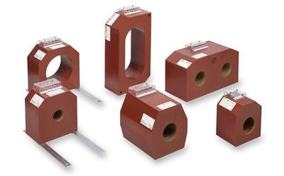
This types of transformers are used so that the ammeters of coils of another instruments are not directly connected to the high current lines or in another words current transformer step down the values by a known ratio so that it can be safely be recorded by a measurement device.
Potential Transformers
They work more or less on the same principle as power or distribution transformer. The only difference is that their capacity is small and ranges anywhere between 100 to 500VA and the low voltage side is generally wound for 115V – 120V
FAQs Related to Transformers
Why do we hear a humming sound near a transformer?
Ans. This happens because of a phenomenon which is scientifically referred as magnetostriction wherein the magnetic steel used in the core expands when magnetized and contracts when demagnetized during the full cycle of the magnetization. Even though they are minuscule proportionally and therefore not normally visible to the naked eye but sufficient enough to cause a vibration and therefore a noise.
Can transformers be operated at voltages other than rated voltages?
Ans. They can be operated below the rated voltage but definitely not above the rated voltage in any case until and unless it is provided with a tap changer. It is to be noted if the transformer is operated below the rated voltage rating then the LVA capacity will also be reduced correspondingly.
Can transformer rated at 60Hz be operated on 50Hz frequency?
Ans. A transformer deigned for 60Hz cannot be operated on a 50Hz service since more losses will occur and will also lead to higher temperature rise and shorter life span. But on the other hand a 50Hz rated transformer can be operated on 60Hz.
Why are transformers rated in kVA not kW?
Ans. When we talk about transformer we have two kind of losses, Iron loss and copper loss. Now since iron losses depend on voltage and copper losses on current, the total losses depend on voltage and current, and no power factor is involved. Transformers are rated in kVA as kW would include power factor.
Can 3 phase transformers be operated in parallel?
Ans. Yes, they can be operated in parallel provided they have the same impedance, voltage rating and same polarity.

